
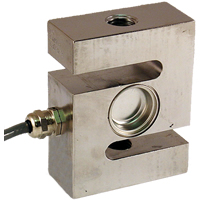
‘S’ Beam Load Cell
We often get asked for fault finding tips and so I’ve put together a simple fault finding guide for a load cell system.
In the previous blog we discussed the load cell part of the system, in this post we discuss the signal conditioning part of the system and provide a summary….
Check signal conditioner excitation voltage
If we measure the excitation voltage without the load cell connected we can check that it is the correct value for our load cell. A lower excitation voltage will give a smaller full scale reading but should still work correctly. A higher excitation voltage could cause the load cell to overheat and alter its characteristics. (If we then measure the excitation with the load cell connected this could show up other potential issues).
Check there aren’t too many load cells connected
We should also ensure that there are not too many load cells connected. Check the total resistance of the load cells either by calculation or measuring with a multimeter. Four 350 Ω load cells in parallel will drop the resistance to about 85 Ω. Check the specification on your signal conditioner to see what the minimum load is.
Short between signal inputs to signal conditioner to simulate zero load
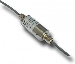
Mantracourt’s Signal Conditioner ‘ALA5’
The next check on the list is to short between the inputs on the signal conditioner. This will simulate a load of zero and should give a zero output (with gain and offset set to one and zero respectively).
Ensure that shunt cal is not active
Some signal conditioners have a shunt cal function. This shunts the output by a fixed value to check the integrity of the load cell, wiring and signal conditioner. If there is any deviation from the last time shunt cal was performed then further investigation is required. If shunt cal is left on then it will completely mess up any real readings. Please note that the shunt cal should never be applied without the load cell connected.
Check six wire or four wire load cell and signal conditioner
If you have a 6-wire signal conditioner with a 4-wire load cell it is important that you link the sense and excitation terminals at the signal conditioner. Otherwise there will be no sense input and therefore no reference point for the signal conditioner. (If you have a 6-wire load cell with a 4-wire signal conditioner it is worth linking the sense and excitation as this will reduce the overall wire resistance).
Check correct power supply to signal conditioner
Check the output from the signal conditioner is what the display needs as its input. Some signal conditioners can output several different protocols which need to be set up correctly.
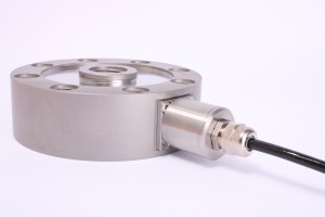
‘Pancake’ Load Cell
Ensure polarity is as required
Check that the positive direction of the load cell corresponds with the positive reading required.
Check gain and offset correctly set
Ensure that gain and offset are set correctly. It may be necessary to try recalibrating at this point if necessary, see the relevant manual. Depending on your setup this could be an absolute nightmare so should be held as a last resort.
The output cabling checks are very similar to the load cell cabling but will be marginally less prone to noise.
Most of the topics that I have covered here are very complex and I have barely scraped the surface. I’ve only very briefly touched on the output and display sections of the system which will be discussed in future blogs.
In Summary:
Check correct output type from signal
Check the signal conditioner has the correct power supply. See the relevant manual.
Load cell
- Check correct wiring connections and colour coding
- Check load cell resistance between excitation +/-
- Check load cell resistance between signal +/-
- Check for mechanical restriction on load cell movement
- Check to see if load cell has been overloaded
Cabling
- Keep distance between load cell and signal conditioner to a minimum
- Keep all sensor cable runs away from inductive loads
- Ensure that you are using twisted pair, screened cable
- Check cable is screened and only connected to ground at one point
- Test cable continuity
Signal conditioner
- Check signal conditioner excitation voltage
- Check there aren’t too many load cells connected
- Short between inputs to signal conditioner to simulate zero load
- Ensure that shunt cal is not active
- Check six wire or four wire load cell and signal conditioner
- Check correct power supply to signal conditioner
- Check correct output type from signal conditioner to display
- Ensure polarity is as required
- Check gain and offset correctly set
Hopefully this has given a helpful starting point for fault finding load cell systems.
For more detailed advice and support please contact us at mantracourt.com
By Tom Lilly, Technical Support Operator at Mantracourt
1 comment
Jonathan,
In follow-up to your conversation with Rob Gray:
Can you e-mail me this document in a word format along with your logo in .jpg format?
Chris Varrecchione
Group Four Transducers, Inc.