


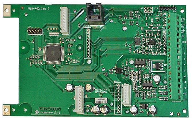
OEM Load Cell Amplifier and Digitiser PCB (LCB20)

.jpg&w=800&h=500&hash=1c8216375c64d0c88b396a4bb21fd553)
.jpg&w=800&h=500&hash=dfd70ca6cb38fef68a3faf45f8f8fbf9)
- PCB version of the load cell amplifier display for weighing (LCA20)
- Simple auto calibration
- 5 V excitation supporting up to 10 x load cells (350 R)
- 0.5 to to 7.8 mV/V sensitivity
- 6 wire input to compensate for barrier and cable losses
- Full digital set-up and calibration using keypad or PC
- Fully isolated analogue outputs 4-20 mA & 0-10 V
- 10 pt linearization
- Three x configurable digital inputs
- Relay outputs:2 setpoints SPCO
- RS485 RS232 digital data output for communications and printing
- Supports MODBUS RTU, ASCII & MANTRABUS
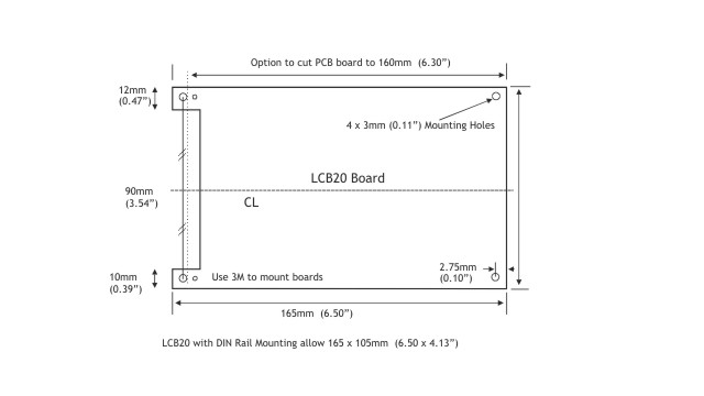
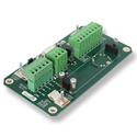
- PCB mounting options include with case (D3) or DIN rail mounted as photo on left (D2)
- The LCB20 also has the option of a stainless steel case
This load cell amplifier and digitiser PCB OEM has undergone a performance and functionality update. It superceeds the LCB PCB, the footprint is the same and it fits neatly into the same size enclosures as before.
The LCB20 is a very flexible digital signal conditioning amplifier for single or multiple load cell applications, offering very easy one-pass calibration and fast setup.
This versatile load cell indicator offers options of local or remote LCD displays, isolated analogue outputs, latching relays or digital outputs for control or weight alarm functions and in-flight compensation for filling applications.
The LCB20 has RS232 or RS485 options, which provide for digital communications (including setup) and can support label or ticket printers.
For a bulkhead cased version of the load cell amplifier and digitiser PCB see model LCA20 load cell amplifier display for weighing.
| Inputs | |
|---|---|
| The input is of the Load Cell/Strain Gauge type. With transducer excitation voltage of 9.6 volts @ 160 mA to drive 10 x 350 R bridges | |
| Compensation by ± sense wires for cable and safety barrier losses down to 3 V excitation | |
| Load cell sensitivity range 0.5 to 7.8mV/V (2 ranges configured from keypad or communications port) | |
| Speed | 10 and 80 Samples Per Second (configured from keypad or communications port) |
| Factory mV/V calibration accuracy | ±0.05% FSD being typical |
| Drift | ± 2 ppm per degree C @ 2.5 mV/V typical |
| Non Linearity before linearization | 10 pt typical |
| Internal Resolution | 20 bit or 1 part in 1,000,000 |
| Noise Free Resolution @ 10 Hz | 17.5 bit or 1 part in 180,000 |
| Contact Inputs | are available for auto tare, print and peak hold reset and are volt free |
| Analogue Outputs | |
| Drive | 4-20mA up to 1Kohm and 0-10 volts up to 2mA |
| Accuracy | ±0.15% FR / ±2% FR before calibration |
| Resolution | as for display up to 13 bits/4.5 digits. Settling time 350mS to within 1% of step change |
| Isolation | ±130 V RMS or DC max to analogue input or any other port |
| Power Supplies | |
| LS1 | 110-120 V AC or 220 / 230 V AC 50-60 Hz 10 W |
| LS3 | 9-32 V DC 10 W isolated |
| Data Retention/Protection | |
| Retention | 20 years for set up values, minimum of 100,000 write cycles |
| Protection of data and function(s) | Watchdog timer giving repeat auto resets. Impending power detection and hold off. Calibration and Toolkit lock feature |
| Other Options & Accessories | |
| 2 Set Points | Output through 5 A 240 V AC SPCO Relays, with a latching option |
| Communications Port | For data transfer or print via :- |
| RS485 | Enabling up to 253 units to be multi dropped |
| RS232 | For 1 to 1 connection and standard printer drive and large displays |
| Printer Operation | By closure of volt free contact or continuous ASCII stream |
| Baud Rates | 2400, 4800, 9600, 19200, 38400, 57600, 76800, 115200 |
| Die Cast Case | Sealed to IP65 with external dimensions of 220 x 120 x 80 mm max |
| Stainless Steel Case | Sealed to IP65, with external dimensions of 224 x 160 x 90 mm |
| PCB Only (Eurocard) (LCB20) | 100 x 160 X 57 mm for rack or customers enclosure |
| Environmental | |
| Storage Temperature | -20 to +70ºC |
| Operating Temperature | -10 to 50ºC |
| Relative Humidity | 95% maximum non condensing |
| CE Environmental Approvals | European EMC Directive 2004/108/EC, Low Voltage Directive 2006/95/EC |
.png&h=40&f=png&far=1&bg=FFFFFF&hash=d1c7fb09682d201239c9925607fc3432)
Documents
- LCA20 Product Sheet : LCA20 & LCB Product Sheet
- LCA20 Manual : LCA20 Load Cell Amplifier with Relay & Data Output, LCB & Toolkit full descriptions
- LCA15 to LCA20 Migration Sheet : Outlining the differences between the LCA15 & LCA20
- LCA15 Manual : LCA15 full descriptions
Software
- LC Toolkit : The LC Toolkit software for Windows will allow a connection with the LCA20 via an optional on-board communications module LC4 or via an optional programming cable PGM1.
Product order options
Please read the following before selecting the options for this product:
LCB20 standard instrument with 4-20 mA/0-10 V analogue outputs. Signed 15 bit 100 mS update, without case.
Starting with the base model LCB20 select the options that you need to configure the device to meet your needs.
| Options | Code |
|---|---|
| Junction Box Active | JBA |
| Base Unit | Code |
| LCB20 PCB Board (only) | LCB20 |
| Comms | Code |
| RS485/232 Communications (supports MODBUS RTU, ASCII, MANTRABUS 1 & MANTRABUS 2) | LC4 |
| Relay Output | Code |
| Relay Output Module 2 Set Points (2 x SPCO 5A 240V AC ) | LR1 |
| Power Supplies | Code |
| AC Power Supply 110/120V, or 220/230V AC | LS1 |
| DC Power Supply 9-32V DC | LS3 |
| Display | Code |
| On Board Programmer | LP1 |
| Remote Hand Held Programmer | LP2 |
| Mounting Enclosure | Code |
| Stainless Steel IP65 Case with Stainless Steel Lid 220 x 160 x 90 mm | LSS |
| Die Cast IP65 Case with Die Cast Lid 220 x 120 x 80mm | LDC |
| DIN Rail Mounting Fixture | D2 |
| IP65 Rated Case and DIN Rail Mounting for DSJ4, LCA, UAB, JBA, SMW | D3 |
| Extended Mounting | Code |
| Transparent Plastic Case Lid | LTL |
| Accessories | Code |
| ABS IP65 Case with Plain ABS Lid 200 x 120 x 75mm | LAB |
| Junction Box PCB (only) Active | JPA |
| Junction Box PCB (only) Passive | JPP |
| PGM1 Programming Lead (no discount available) | PGM1 |
These are the following industries and applications in which this product has been used:
- Industrial Processing - Plant Processing
Mount Board for a Single Digital Load Cell Converter
.jpg&w=125&h=125&far=1&bg=FFFFFF&hash=02d2ea5ec469f69940b458cb534eb000)
Load Cell Amplifier with Relays Data Port & Display for Weighing
- Q: Is DIN rail mounting optional?
A: Yes
- Q: How do I factory reset a ADP / ADW / LCA20 / SMW?
A: Hold down the Scroll and reset key and then power cycle the unit.
* All settings will be reset, including calibration.- Q: What Protocols are available with the LCA20?
A: There are 4 Protocols
CP=128 = Mantrabus 1 a hex based protocol. Most popular, easiest to deal with from programming point of view.
CP=131 = Mantrabus 2 updated version of Mantrabus1
CP=133 = Mantra ASCII 2 based protocol designed for old teletype machines, looks easier but actually more complicated to programme.
CP = 132 Modbus RTU used a lot in PLCs. 3rd Party S/W available. Hex based.
Or alternatively set CP=127 and the device will transmit an ASCII string every display update (used for continuous printout to either printer or display.- Q: Does stainless steel case for LCA20 have stainless steel glands?
A: No plastic PG9 glands.
- Q: Does the 4-20 mA output on an LCA20 have galvanic separation?
A: No but it does have electrical isolation up to ±130V RMS
- Q: What is the maximum length of cable we could connect between a LCA20 unit and a load cell unit?
A: It would depend on many different factors:
The quality of the cable
The type of cable
Whether it was 4 or 6 core
The number of load cells
Environment
Interference
With the best quality of cable in an ideal environment and with little or no interference we have had operating at 200 metres.- Q: How do you view the live reading on the LCA20 without Auto Tare and having to calibrate again?
Go to the 'measurement' section in the LCA Toolkit.
Note the reading in the 'Tare' value box and then change the value to zero. Click on the 'Tare' button and the unit will display live reading.Alternatively, using the keypad:
Go into the menu and pick AT Mnemonic.
Note the reading down and then set to zero.
Press return and then the unit will display live reading.
To reset Auto Tare re enter value in AT Mnemonic screen which you noted down.- Q: Is it possible to connect two LCA20s to one load cell?
How would the scaling of each remain stable in the event of a failure of one or the other ?
Can the output of the load cell be connected to both LCAs? With perhaps a resistor network holding the input of the second to a reference ?A: This is done using 6 wire, with the second LCA20 as 5 wire (no "+" excitation).
You could have two 6 wire with two blocking diodes (for redundancy).
Or a separate power supply and two 5 wires.- Q: Can I use a laptop to set up the LCA20?
A: Yes, by means of the optional PGM1 Programming Cable and the LCA Toolkit. The option to use the LCA20 keypad is also available.
- Q: LCA20 / SMW can they handle tension and compression?
A: Yes
- Q: How do I factory reset a ADP / ADW / LCA20 / SMW?
A: Hold down the Scroll and reset key and then power cycle the unit.
* All settings will be reset, including calibration.- For more 'Frequently Asked Questions' please see our Knowledge Centre