In the last decade, advances in performance monitoring capabilities have improved industry’s ability to analyse large volumes of data in real-time. However, what approach should businesses take when maintaining physical data records and backups becomes too costly or time consuming? This whitepaper breaks down how site managers can use cloud-based platforms to optimise their data monitoring systems, reduce operating costs and save time. Furthermore, it explains how to achieve the best results from a wireless sensor installation.
Optimising
data monitoring protocols using cloud-based a platform
Research company Fortune Business Insights predicts
that the global market size for IoT-connected devices will reach $1,463.19
billion by 2027, growing at a compound annual growth rate (CAGR) of 24.9 per
cent. It also estimates that the industrial automation
market worldwide will reach $296.7 billion by 2026 — almost double the value in
2019. These market growths have been accelerated by companies being forced to
adjust to a new digital reality much earlier than expected because of the
coronavirus pandemic.
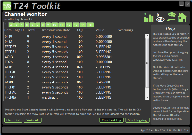
Wireless
sensors, particularly those monitoring large or complex processes, can gather
lots of data, which is then stored in a format such as CSV for analysing in a
spreadsheet. Manually analysing all this
data can sometimes be laborious and time consuming.
It’s
clear that asset managers need a better place to store, visualise and monitor
their data repository, combined with a customisable automated alerts system to
let them know when there is a problem so they can act immediately to protect
key assets.
Taking
data to the cloud
In
the era of Industry 4.0 and the widespread adoption of Industrial Internet of
Things (IIoT) technologies, the benefits of installing cloud-based remote
monitoring systems across a facility are more compelling than ever.
“It
is becoming increasingly clear that remote monitoring is the most convenient
and cost-effective way of managing system performance across an industrial
facility.”
By
remotely monitoring and managing assets over long periods of time, industry
reaps the rewards in the form of lower operating costs, faster response times
and better service levels.
Cloud-based
remote monitoring systems, like Mantracourt’s SensorSpace® platform, are
becoming increasingly popular across a variety of industrial sectors including
agriculture, food and beverage and construction. SensorSpace® is a bespoke
cloud-based platform that allows customers to login from anywhere in the world
using a desktop or mobile device and remotely monitor system status and asset
performance information relayed by Mantracourt’s T24 wireless telemetry system.
The system’s dashboard can be as simple or as complicated as users need it to
be, from a simple numerical display of operational parameters to in-depth
overlays, charts and graphs showing live and historical data.
SensorSpace®
is already making an impact across key industrial sectors. For example, it
allows site managers in an agriculture setting to monitor for humidity or
pressure changes in a grain silo. Any undetected change to the conditions in a
silo may threaten the integrity of the product, as well as the safety of the
container. In the event of a problem, the appropriate personnel can be notified
immediately via SMS, email or app-based alerts so appropriate action can be
taken quickly.
Site
managers are also recognising the benefits of being able to store and analyse
all their data in one easy-to-use umbrella platform, rather than having to
consolidate several complex spreadsheets. Having the ability to customise your
data dashboards, from simple numerical displays of operational parameters to
in-depth graphical summaries, will inevitably save a lot of time.
Furthermore, there are financial benefits
associated compared to data monitoring methods. For example, a company who
provides heavy industrial jacking applications for the construction industry
must precisely pre-set an array of hydraulic jacks to a specific stroke length
at a specific pressure. The static data from these installs can be fed directly
to SensorSpace for round the clock remote monitoring. Financially, the
installation can be quicker because a wireless system removes the need for
running cables and the company removes the need for sending personnel to site
for data monitoring and extraction. There may also be cases where the number of
jacks were able to be reduced on site.
While
most of the world was under strict restrictions because of the coronavirus
pandemic, site visits and manual system inspections could not proceed as
normal. In many cases, businesses that relied on these to capture operational
data across their facility were unable to regularly collect system data over that
time.
“SensorSpace®
provides asset managers with the ability to monitor and analyse system
performance 24/7, even if they’re working from home.”
Top tips for a successful wireless sensor
installation
In many cases, remote monitoring technology goes hand-in-hand with wireless sensor technology. Modern wireless sensors provide precise test and measurement capabilities in a portable and flexible package, making them an appealing choice for asset managers looking to easily gather data from manufacturing equipment. However, to reap the full benefits of wireless technology, there are a few important steps to follow during set up.
Undertake a site survey
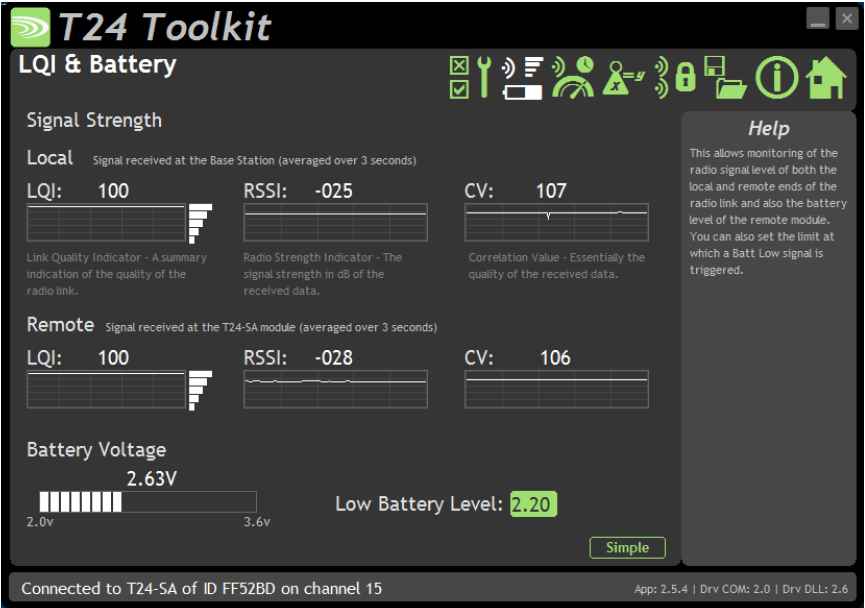
A sensor’s signal strength and data capture
capabilities should be assessed on-site. To do this, after ensuring that the
sensor is in place and transmitting, the site can be explored with a receiver,
such as one of Mantracourt’s T24 handheld receivers.
This allows users to identify any dead spots
and plan their layout accordingly. It’s important to remember that the ground
can absorb a large portion of the signal, so both the transmitter and the
receiver should be located above ground.
Other obstacles,
such as concrete or brick walls, metal cladding, ironwork, metal meshes up to
100 mm thick, and, surprisingly, trees in leaf that contain a lot of water, can
impact the signal strength. If
additional coverage is required, a repeater can help extend the sensor’s range
and bypass obstacles. It’s also important to consider the presence of
future obstacles that might not be present during the installation — for
example, you wouldn’t want to position a wireless sensor behind a spot where
lorries often park, or along a train track.
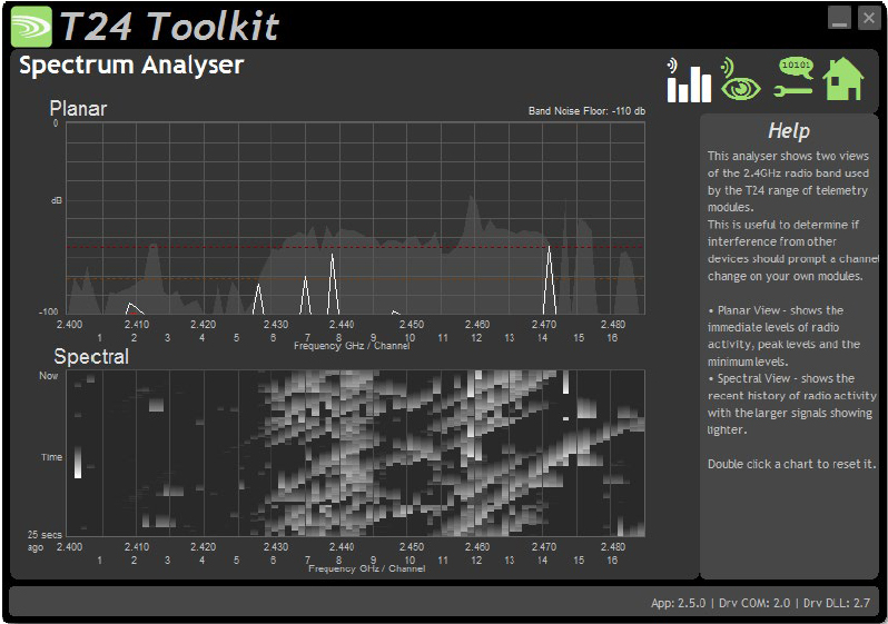
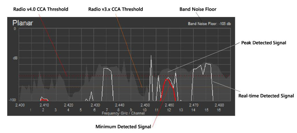
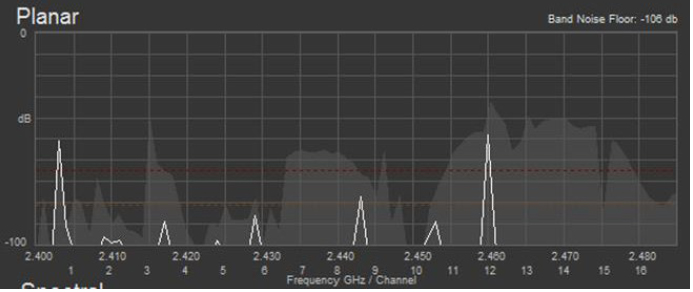
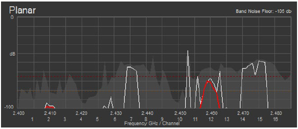
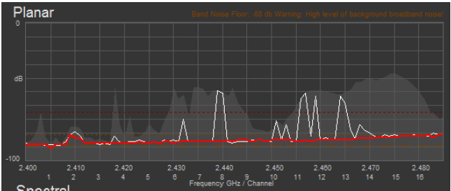
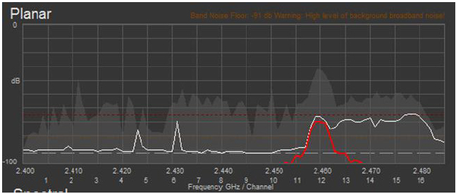
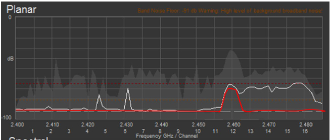
Radio interference is usually not a concern,
because licensed low power devices that use transmission formats such as 2.4
GHz are surprisingly tolerant to common interference sources. However, having
multiple sensors can block or slow transmission data, particularly if they are
on the same channel. For these reasons, Mantracourt’s T24 products have an
error checking function to ensure that data is transmitted correctly. As well
as using a clear channel, users can easily configure the rate at which data is
sent to reduce the competition for bandwidth between transmitting sensors.
Extend your sensor’s lifespan
Wireless sensors can spend most of their
life in low power mode and activate to record measurements and transmit data
when needed, meaning that their internal battery can last for several years.
However, in some instances when faster transmission rates are necessary and no
permanent supply is available,
manufacturers can use a solar panel or energy harvesting system such as
Mantracourt’s Power Pack 1 and Solar Panel 1.
For sensors that operate in particularly
harsh environments, an enclosure can prevent damage from water or aggressive
chemicals. This is why each of Mantracourt’s wireless transmitter modules can
be ordered in one of three IP rated enclosures. When choosing or designing an
enclosure, it’s important to remember that the radio signal will need an
aperture to escape, such as a small fiberglass window. Users should also
remember to tighten up any cable glands and use a drip loop when connecting
cables to sensors, transmitter and repeaters to prevent moisture from entering.
Think about your data
Storing raw data locally is simple but
limits live analytical capabilities. However, thanks to cloud-based remote
monitoring platforms like SensorSpace® data can be analysed in real-time,
allowing you to quickly identify trends and take action when needed.
“Following these steps, manufacturers can
easily measure variables such as linear movement, wind speed, temperature,
loads or torque.”
The flexibility and ease of installation of wireless sensors means that data can be collected efficiently and cost-effectively, saving money and improving processes in the long run. Also, it allows for more flexibility in ongoing projects where you might only begin with a small number of sensors and increase this down the line. In these situations, you can easily add more wireless sensors, connected to the cloud-based monitoring system, without the need for costly and disruptive cable installations.
To find out more about Mantracourt’s T24 wireless telemetry system or SensorSpace cloud platform, visit the Mantracourt website at http://www.mantracourt.com or contact our technical sales team today.