


Digital Sensor Card USB – Potentiometer Input (DSCUSB-PT)

- High precision potentiometer input providing superior performance
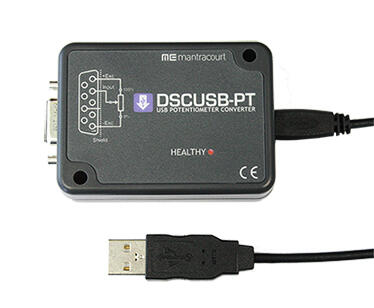
- Simple USB plug and play device connects to a PC directly, allowing quick setup
- Works with free DSCUSB toolkit software for fast and accurate measurement
- 7 point linearization and optional temperature compensation
- Configuration and calibration can be saved and restored for security of setup
- Log up to 24 devices using DSC 24 Channel Logging Software
- Supplied with 1.5m USB to Micro USB lead
- OEM PCB version available
- Windows driver DLL’s available
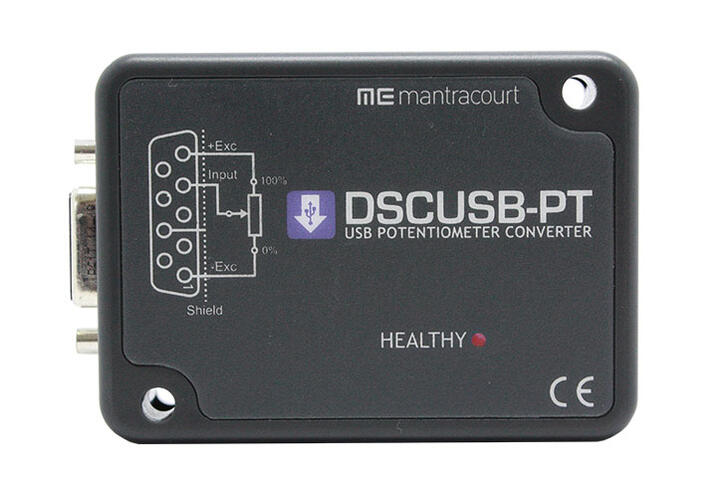
The DSCUSB-PT is a compact, high-precision potentiometer input module; converting a resistance based input (potentiometer) to a digital output. Can be used with resistance based sensors to indicate position, rotation and angle. Aimed at applications which require high accuracy.
Simply by plugging the device into a PC, data can be extracted from the potentiometer input to the DSCUSB-PT for a wide range of applications. This is achieved using the DSCUSB Toolkit software, which is a simple configuration tool designed specifically for configuring DSCUSB modules. It allows configuration, calibration, logging and parameter management of the modules.
The output is factory calibrated to give an output from between 0% and 100% but this can be scaled by the system integrator or the user to give engineering units instead.
This free-standing module is fitted with 9-way ‘D’ type socket for potentiometer and optional temperature sensor connections. A micro USB socket accepts a USB lead with type ’A’ connector at the PC end.

Documents
- DSCUSB-PT Product Sheet : Digital Sensor Card USB - Potentiometer Input Product specifications and Toolkit Information
- DSCUSB-PT Standard Manual
- DSCUSB-PT Advanced Manual
Software
- DSCUSB Toolkit : Version 04.06.00 This toolkit allows configuration, calibration, logging and parameter management of the DSCUSB, DSCUSB-PT, DSCSUASC and DSCSUEASC modules.
- DSC 24 Channel Logging : Version 1.3.2 View and log data from up to 24 DSC, DLC or DSCUSB modules.
- Driver DLL DSCUSB : Version 2.2 DSCUSBDrvxx.DLL is a standard Windows DLL that can be used to help your own Windows PC applications communicate with DSC USB instruments DSCSUASC and DSCSUEASC.
- DSC Fixed COM Ports : This software ensures that all DSCUSB modules plugged into the PC are allocated the same COM port. This is useful for OEM scenarios where many modules are connected for production purposes.
Product order options
| Options | Code |
|---|---|
| Potentiometer to USB Converter | DSCUSB-PT |
| Potentiometer to USB Converter - No case or field conns PCB only | DSCUSB-PTOEM1 |
- Q: How do I communicate with the USB device?
A: Using a simple ‘Virtual Com Port’, the DSCUSB-PT communicates as if the device is connected to a serial port. The device addressing allows up to multiple devices.
- Q: Is temperature sensing available on the DSCUSB-PT
A: An optional temperature sensor module (DTEMP) is available which will enable an advanced 5-point temperature-compensation of measurements.
- Q: Is there Linearity compensation in the DSCUSB-PT?
A: Advanced 7-point linearity compensation available as standard.
- Q: How stable is the DSCUSB-PT device?
A: 10ppm/°C basic accuracy (equates to 16 bit resolution).
- Q: Are there self-diagnostics capabilities?
A: Continuous monitoring on the DSCUSB for faults such as over/under-temperature, power failure. All fault warnings are retained on power-fail.
- Q: What are the output options of the DSCUSB-PT?
A: We currently only offer the device in ASCII protocol.
- Q: Tell me about DSCUSB-PT low current?
A: Functions as a ‘Low Power Device’ i.e. draws less than 100mA (one unit load) when connected to a 500 Ohm load sensor.
- Q: Can I use the DSCUSB-PT with my own software?
A: Yes. The DSCUSB-PT appears as a virtual com port. The protocol is ASCII and is described in the advanced manual.
- Q: Can I check the input of the DSCUSB-PT is working correctly?
A: Yes. There is a 50% reference output on pin 3 of the D-Type connector. Disconnect the sensor and connect pin 3 to pin 4 of the D-Type connector. This should give a 50% value of ±1%