


ATEX Certificated Miniature Load Cell Amplifier with 4-20 mA 2 Wire Loop Powered OutputICA5ATEX
SKU: ICA5ATEX
Description
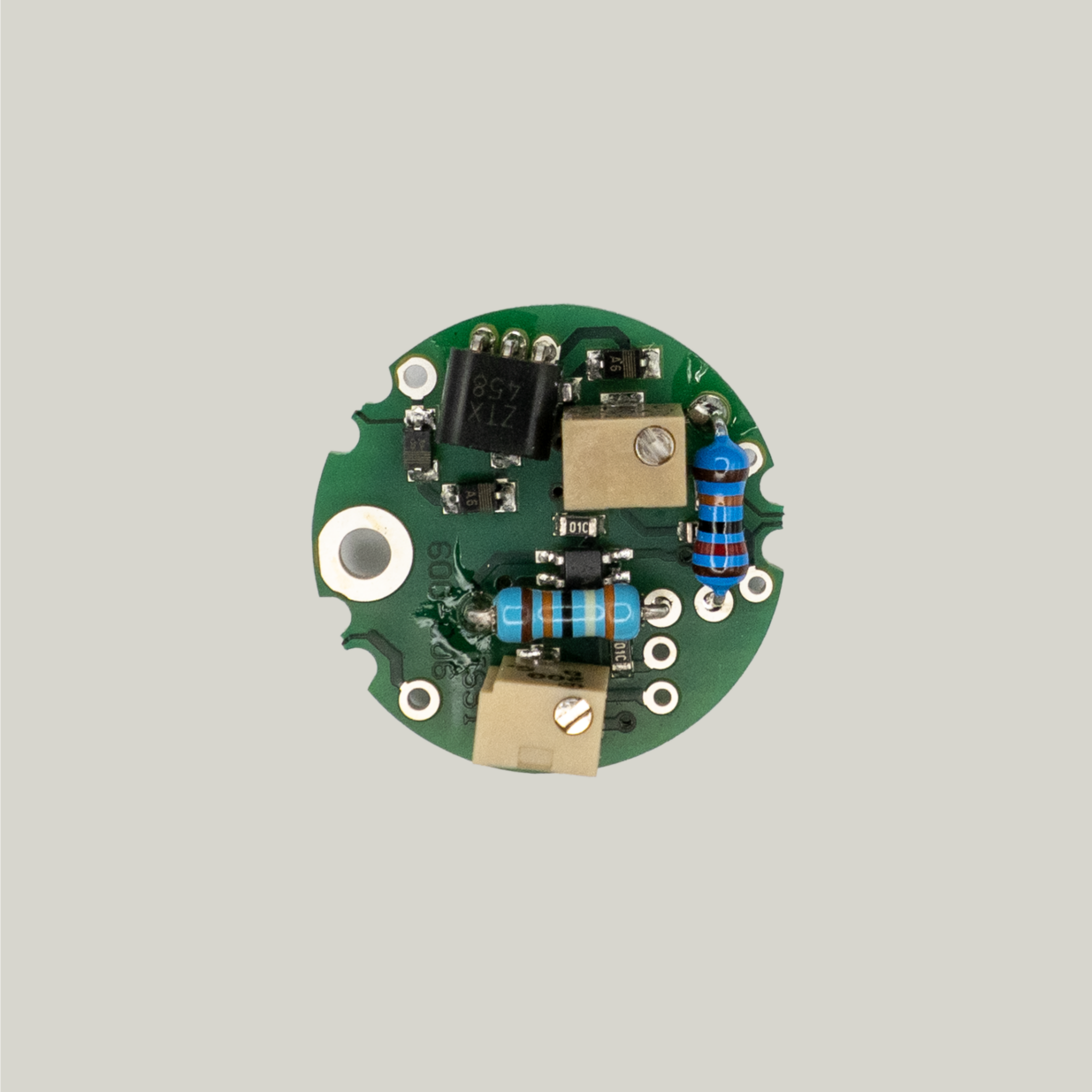
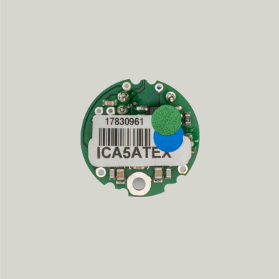
ICA5ATEX – ATEX-Certified Miniature Load Cell Amplifier (4–20 mA Loop-Powered Output)
The ICA5ATEX is a high-performance ATEX-certified miniature strain gauge amplifier designed for safe operation within Hazardous Zones 0, 1 & 2. It is the ideal solution for OEM customers seeking to embed a certified signal-conditioning module directly within their load cells, pressure sensors, or other strain-based transducers.
Providing a 2-wire 4–20 mA loop-powered analogue output, the ICA5ATEX is designed to connect in-line with strain gauge elements to deliver stable, noise-immune measurement signals over long distances. It is intrinsically safe to EN60079-11 standards (formerly EN50020), ensuring compliance for use in explosive atmospheres.
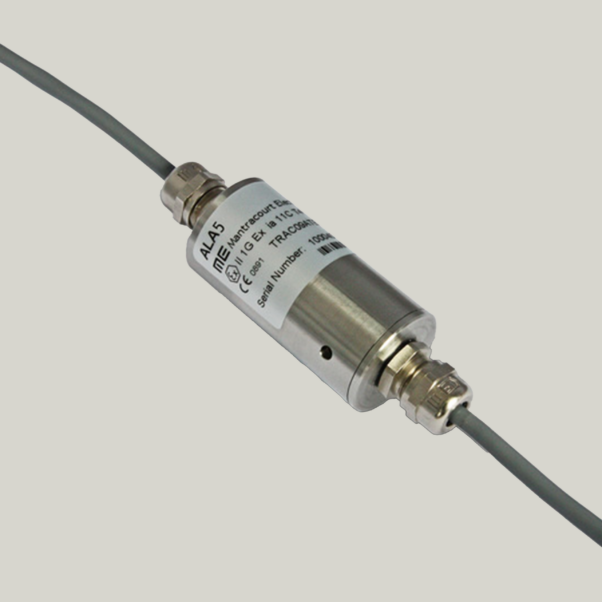
The ICA5ATEX may be housed within a stainless steel IP67 NEMA 4 EMC-protected enclosure, such as the ALA5, which is supplied with 1 m of strain gauge cable and 5 m of output cable. The amplifier is suitable for inline or embedded integration, offering exceptional performance in challenging environments.
Please note: the ICA5ATEX is approved for incorporation into load cells and other enclosures, but not for standalone use without proper housing in hazardous zones.
The ICA range includes:
-
ICA1H, ICA2H, ICA3H, ICA4H, ICA6H – High-performance OEM amplifier variants
-
ICA5S – Industrial-grade version for general installations
-
ICA5ATEX – Intrinsically safe ATEX-certified version for hazardous areas
An optional ILE (In-Line Enclosure) is also available for use in non-hazardous areas, enabling standard load cells to be converted into conditioned-output sensors.
Product Features & Benefits
- ATEX certificated amplifier for hazardous zones 0, 1 & 2
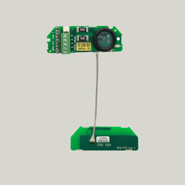
- Miniature PCB format for fitting inside sensors, 19 mm diameter, 7.6 mm height
- 2 wire current loop 4-20 mA output
- Low interaction between the trimmers makes calibration fast and easy
- High speed 1000 Hz
- User selectable span and zero resistors
- Robust design, high noise immunity & reverse polarity protected
- Option of an in-line enclosure ATEX certified load cell amplifier
Specifications
Parameter
|
Min |
Typ |
Max |
Units |
Notes |
Electrical & Environmental
|
|||||
| Supply Voltage Range | 9 | 24 | 28 | Volts | |
| Operating Current | 4 | – | 20 | mA | |
| Operating temperature range | -40 | – | 85 | ºC | |
| Storage temperature range | -40 | – | 125 | ºC | |
| Reverse polarity protection
|
– | – | -28 | Volts | |
Measurement
|
|||||
| Bridge excitation | 1.05 | 1.11 | 1.16 | Volts | 1000 Ohm load cell – Typically 0.53V for 350 Ohm cell |
| Bridge impedance | 350 | 1000 | 5000 | Ohms | Recommended bridge impedance is 1000 Ohms |
| Bridge sensitivity | 0.5 | 2.5 | 55 | mV/V | The factory setting is the typical value, with other values possible via an alternate calibration resistor. |
| Output current range | 4 | – | 20 | mA | |
| Output load | – | – | 300 | Ohms | Limited by the 300Ω barrier impedance |
| Bandwidth | DC | – | 1000 | Hz | |
| Zero adjustment | – | ±2 | – | %FR | 1000 Ohms load cell – change R1 to suit other load cell impedances. |
| Span adjustment | – | ±8 | – | %FR | |
| Linearity | – | 0.02 | – | %FR | |
| Zero temp stability | – | 0.001 | 0.005 | ±%FR/ºC | |
| Span temp stability
|
– | 0.007 | 0.014 | ±%FR/ºC | |
General Notes:
|
|||||
| Note: The voltage between either of the power supply connections and the load cell shield should not exceed 50V. Any leakage will be greater than 10M Ohms. | |||||
| FR = Full Range
|
|||||
Environmental
|
|||||
| Storage Temperature | -40 to +85ºC | ||||
| Operating Temperature | -40 to +85ºC | ||||
| Relative Humidity | 95% maximum non condensing | ||||
| CE Environmental Approvals | European EMC Directive 2004/108/EC | ||||
Dimensions

Downloads
Videos
FAQ
| Q | What are the different ATEX zones? |
| A | Zone 0 – Permanently or frequently hazardous over long periods.
Zone 1 – Occasionally hazardous. Zone 2 – Rarely or temporarily hazardous Safe Zone – No hazard |
| Q | What Strain Gauge parameters is the ALA5 designed for? |
| A | Designed for a 1k bridge, however, 350R can be used at the expense of noise and drift performance due to the reduced excitation voltage on the bridge. It is factory set for 2.5mV/V. |
| Q | What do the ATEX markings mean? |
| A | II 1 G Ex ia IIC T4 Tamb = -40°C to +85°C CE0891 TRAC09ATEX1xxxX ATEX Marking detailsEx – Explosion protection Certification Code detailsEx – Explosion protection |
| Q | Are there different mV/V settings available? |
| A | The sensitivity can be set between 0.5 mV/V and 55 mV/V by changing the SPAN (gain) resistor. Please enquire with our Sales team for more info. |
| Q | Can I extend the output cable on the ALA5? |
| A | Yes by use of an ATEX approved junction box. Please refer to the manual for the EC examination certificate detailing the maximum allowable cable capacitance and inductance. |
| Q | What is the maximum cable length for the load cell connections? |
| A | Maximum is 2 metres. |
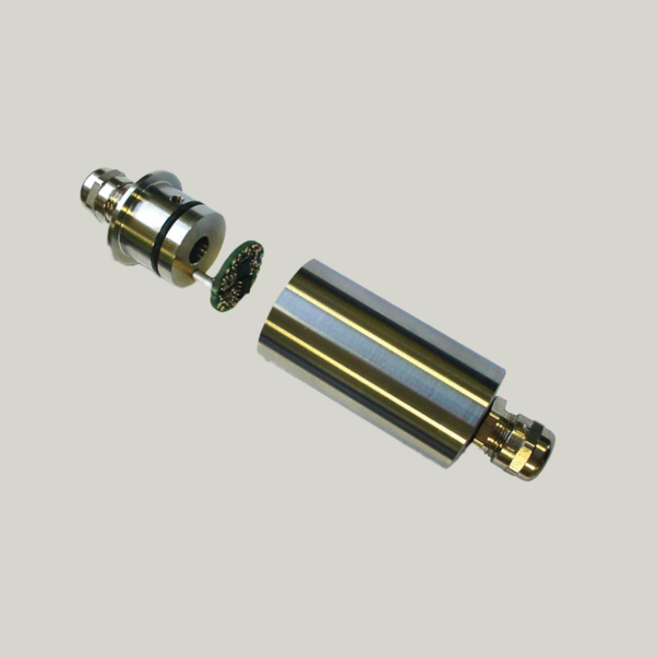
| Q | Can I embed the OEM ALA5 device into my own loadcell? |
| A | Yes, the ICA5ATEX amplifier is designed to fit into a pocket in a certified loadcell. Please note: OEM customers must hold a notified body Quality Assurance Notification (QAN) and ensure that the load cell and amplifier assembly is submitted for ATEX certification by an appropriate body. |
| Q | What is ATEX? |
| A | The term ‘ATEX’ comes from the French word ‘atmosphére explosibles’. It is the name commonly given to the framework for controlling explosive atmospheres and the standards of equipment and protective systems used in them. It is based on the requirements of two European Directives. One that applies to equipment manufacturers and another for its end users, both Directives came into effect on 1 July 2003.
The ATEX regulation removes the need for separate testing by joining the technical and legal standards for manufacturing of equipment that may potentially be used in explosive atmospheres . ATEX regulations apply to all equipment intended for use in explosive atmospheres, whether electrical or mechanical, and also protective systems. Manufacturers must ensure that their products meet essential health and safely requirements and undergo appropriate conformity procedures. |
| Q | Is a barrier needed for Zones 1 and 2? |
| A | Yes, a barrier is needed for all ATEX installations. Please contact us for more information. |
Need Assistance?
Get in touch and we’ll help you
to identify the right solution.