Strain Gauge Signal Conditioner for Load Cells with AmplifierSGA
SKU: SGA
Description
The strain gauge amplifier is a high performance signal conditioner for single or multiple strain gauge bridge sensors such as load, force, pressure and torque.
The SGA A&D provides strain gauge signal conditioning for load cells and offers a wide bandwidth and a wide input signal range. The device can be powered from AC or DC supplies providing excitation for up to four x 350 Ohm strain gauge bridges.
The conditioned output signal can be selected from 0-20 mA, 4-20 mA, 0-10 V, 0-5 V, ±5 V or ±10 V.
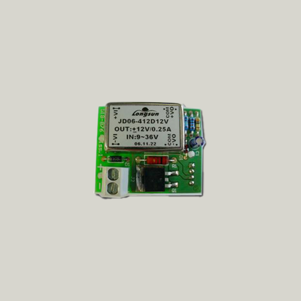
Options include: Isolated DC supply and DIN rail mount.
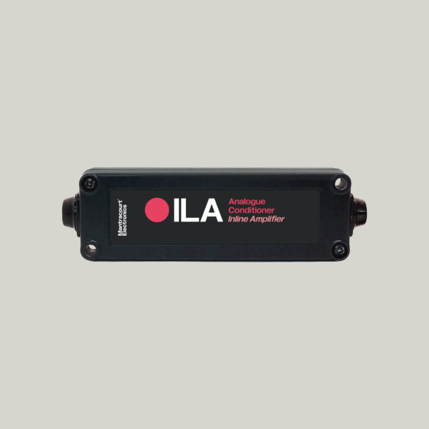
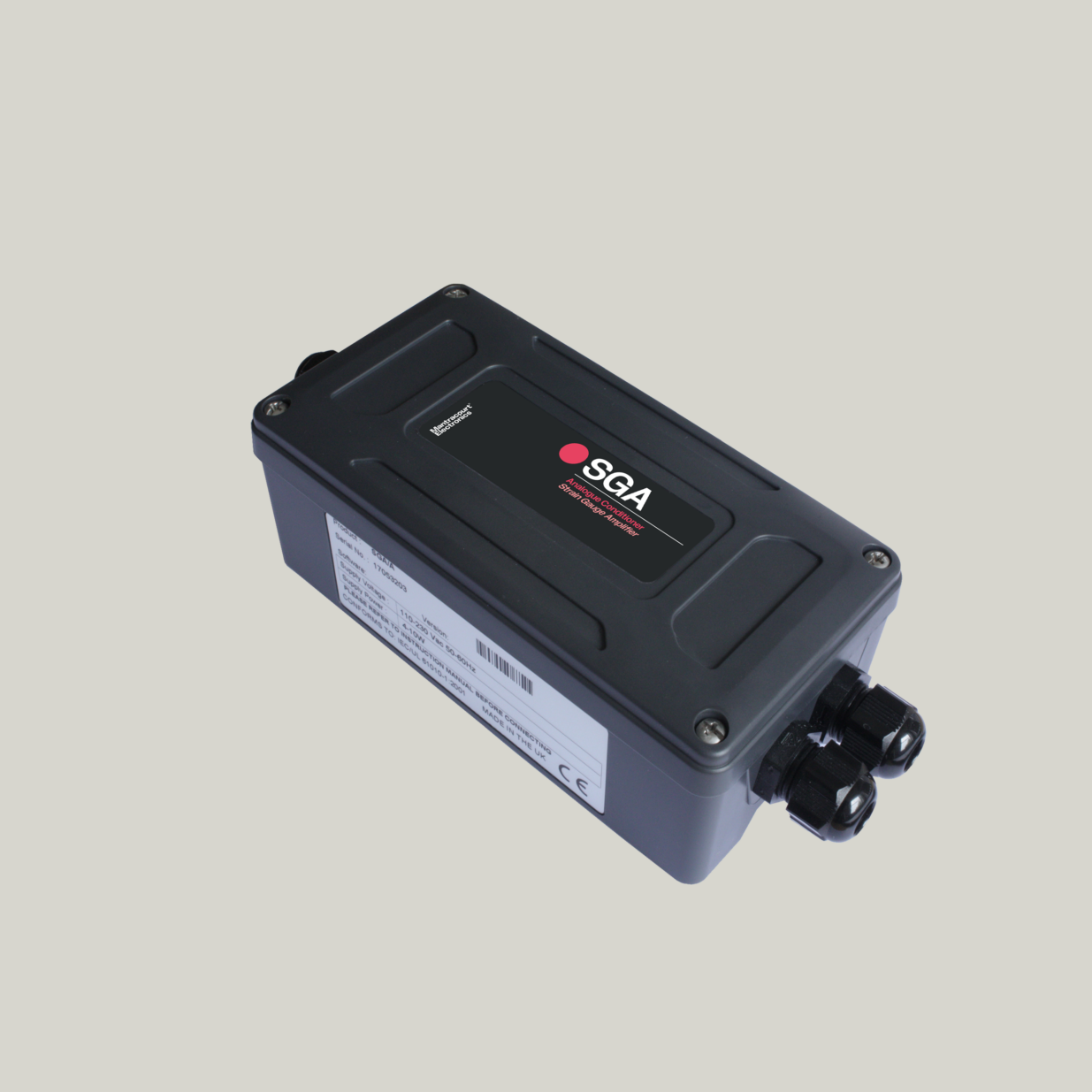
Supplied in a waterproof IP67 NEMA4 bulkhead mountable case and is available with AC or DC power supply options. The strain gauge signal conditioning module is robust and fully CE compliant.
For a digital version of the strain gauge signal conditioning module with set point relays, communications and display options please see our load cell amplifier display for weighing LCA20.
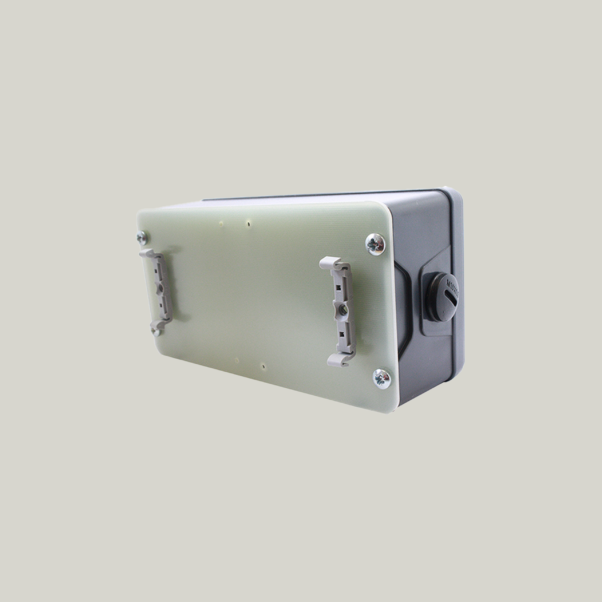
The SGA can be mounted on a DIN Rail using a D4 base plate listed as an optional accessory for your SGA.
Also avaliable as SGA-D-Y Strain Gauge Amplifier (18-24VDC, board only). Minimum order quantity (MOQ) applies.
Product Features & Benefits
- Strain gauge amplifier ideal for load cell signal conditioning
- Bridge excitation of 10 V DC with drive for four 350 Ohm load cells
- Conditioned output signal can be selected from 0-20 mA, 4-20 mA, 0-10 V, 0-5 V, ±5 V or ±10 V
- 1 – 5 kHz adjusted filter for test & measurement applications
- Selectable sensitivity from 0.1 to 30 mV/V using switches and fine trim potentiometer
- Switch selectable offset ±70% FS using switches and fine trim potentiometer
- User selectable analogue output in standard voltage or current format
- The SGA comes complete with case, with option of DIN rail mounted case accessort (D4) sold seperately.
Specifications
| Parameter | ||||
|---|---|---|---|---|
| Min | Typical | Max | Units | |
| Power supply (SGA/A):- (110/230Vac) 50 – 60Hz | 99/198 | 110/230 | 126/253 | V AC |
| Power supply DC :- | 18 | 24 | V DC (Note: 1) | |
| Power supply IS12/24 – Isolated | 9 | 36 | V DC | |
| Power supply current DC :- (depends on loading) | 50 | 90 | 200 | mA |
| Bridge excitation (10 V range) | 9.75 | 10 | 10.25 | V |
| Bridge excitation (5 V range) | 4.85 | 5 | 5.15 | V |
| Bridge resistance | 85 | Ohms | ||
| Bridge sensitivity (Switchable) | 0.06 | 30 | mV/V | |
| Gain adjustment (Pot – fine adj.) | 0.06 | 1.0 | mV/V (Note: 2) | |
| Offset adjustment (Pot – fine adj.) | -1.25 | +1.25 | %FR (FR=Full Range) | |
| Offset adjustment (Switchable – coarse adj) | ±1.25 | ±80 | %FR | |
| Output load (Voltage output) | 2 | mA | ||
| Output load (Current output) | 0 | 500 | Ohms | |
| Bandwidth (No filter and > 2mV/V) – 3dB point | DC | 6000 | Hz | |
| Filter cut-off (Switchable ranges) – 3dB point | 1 | 5000 | Hz | |
| Zero temperature coefficient at 2.5mV/V) | 0.002 | %FR/ ºC at 2.5mV/V FR | ||
| Span temperature coefficient | 0.007 | %FR/ ºC | ||
| Linearity | 0.03 | %FR | ||
| Gain stability -1st 1000 Hours | 0.2 | %FR | ||
| Gain stability – 2nd 1000 Hours | 0.1 | %FR | ||
| 90 day Offset stability | 3.3 | uV | ||
| Output load stability gain (0 – 100%) | 0.01 | %FR | ||
| Output load stability offset (0 – 100%) | 0.01 | %FR | ||
| Power supply rejection gain (0 – 100%) | 0.01 | %FR | ||
| Power supply rejection offset (0 – 100%) | 0.01 | %FR | ||
| Operating temperature range | -10 | 50 | ºC | |
| Storage temperature range | -20 | 70 | ºC | |
| Humidity | 95 | % | ||
Note:1 18V max at full load.
Note:2 Depends on sensitivity settings
| Output Options Set by On-Board Switch | |
|---|---|
| ±10V, ±5V, 0-10V, 0-5V, 0-20mA, 4-20mA |
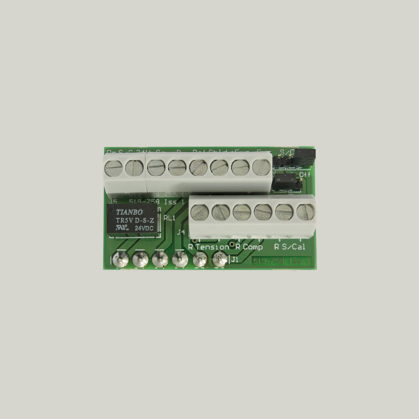
| Connections | |
|---|---|
| Field screw terminals – 2.5mm² rising clamp |
| Enclosure | |
|---|---|
| ABS case 160 x 80 x 55 sealed to IP67 fitted with 3 off cable glands |
| Controls | |
|---|---|
| Gain pot, Offset pot, Coarse gain switches, Coarse offset switches, Filter cut-off switches, Output mode switch |
| Environmental | |
|---|---|
| CE Environmental Approvals; European EMC Directive 2004/108/EC, Low Voltage directive 2006/95/EC |
Dimensions

Downloads
FAQ
| Q | Can the SGA be mounted on a DIN Rail? |
| A | Yes, the SGA can be mounted on a DIN Rail using a D4 base plate listed as an optional accessory for your SGA. |
| Q | Does the SGA have shunt calibration? |
| A | The SGA has an onboard shunt calibration function. This shunts one arm of the connected load cell to produce a known change in the output which can be used for calibration or checking load cell integrity (or associated wiring). |
| Q | Does the SGA / LVDT lose its calibration if you switch it from 4-20 mA to 0-10 V? |
| A | Yes |
Need Assistance?
Get in touch and we’ll help you
to identify the right solution.